If you work with time and frequency calibration, you know that a calibration label isn’t just a sticker—it’s a promise. Every manufacturer, telecom provider, research lab, or aerospace team that sends you a device to calibrate relies on two things: that our calibration process is accurate, and that they can trust the results we send back. As the lead calibration engineer here (and one of the people you’ll get on the phone if you have questions about a report), I’ve spent the last 12 years walking teams through verifying their own results after they get our calibration data. Most of the questions I get aren’t about how to perform calibration—it’s about how to be sure that calibration actually worked. Time Frequency Calibration
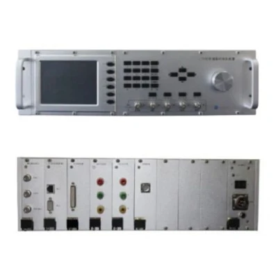
A few months back, a customer from a regional telecom network sent me an email that stuck with me. They had received a calibration report for their primary GPS-disciplined oscillator (GPSDO) after we tuned its 10 MHz output. Their team ran a quick test overnight using a second, lab-grade 10 MHz reference they had in-house, and got readings that were within our report’s stated uncertainty. But when they ran a 72-hour test, they noticed a tiny drift—something they thought might be calibration error, or maybe their own test setup. They asked, “How do I know if the calibration is good, or if I’m the one measuring it wrong?” That’s the heart of this topic: verifying time frequency calibration results isn’t about checking our math—it’s about matching your test setup to the rigor of our process, so you’re comparing apples to apples.
Let’s start with the basics, because this is where most people slip up. When we calibrate a device, we use a reference that is traceable to national metrology institutes (NMIs)—think NIST in the U.S., PTB in Germany, NPL in the UK. That means our reference’s time and frequency accuracy is documented, and every step of its calibration is recorded back to a primary standard. When you verify our results, your first job is to make sure your test setup is also traceable. I can’t tell you how many times I’ve seen teams use a “lab reference” that was calibrated 10 years ago, or a cheap signal generator that they picked up on eBay because they thought “10 MHz is 10 MHz.” That’s a mistake. If your reference isn’t traceable, your verification test is just a guess.
Traceability isn’t a checkbox—it’s a chain. Your chain starts at a primary NMI standard, moves to a secondary reference calibrated to that NMI standard, then to your in-house test setup, and finally to the device you just had calibrated. If any link is broken, your verification result is meaningless. For example: if you use a signal generator to test a calibrated oscillator, that generator must have a calibration certificate that links back to an NMI standard, and its uncertainty must be lower than the uncertainty we stated in our calibration report. Our reports always list our expanded uncertainty (that’s the U value you see at the bottom, with a coverage factor of k=2, meaning 95% confidence). When you set up your verification, your test system’s total uncertainty needs to be at least three times smaller than that number. If our uncertainty is 1 x 10^-12, your test setup’s uncertainty needs to be less than ~0.3 x 10^-12. If it’s not, you can’t measure a true drift in the calibrated device—your own test noise will mask it.
Next, pick the right test duration. This is the second big mistake the telecom team made earlier. Short tests (like an hour or overnight) are great for catching gross errors, but they miss subtle drift that happens over days. Let’s break it down: oscillators have two types of drift—short-term (phase noise, jitter, variations over milliseconds to hours) and long-term (aging, changes over days to months). Our calibration process accounts for both, so your verification needs to cover both too. For most devices we calibrate—GPSDOs, OCXOs, TCXOs, rubidium standards—I recommend a 72-hour continuous test. Why 72 hours? Because that’s the window where most calibrated devices stabilize after tuning, and it’s long enough to separate test noise from real drift. If you’re verifying a primary rubidium standard, you might need a week, because those have slower aging rates. If you only run a 2-hour test, you might see a blip from your test setup’s power supply noise and think the calibration failed, when it’s just your measurement, not the device.
When you run that test, what exactly are you measuring? Let’s get specific, because vague tests give vague results. The key parameter for frequency calibration is the fractional frequency offset (Δf/f), written in parts per notation—like parts per 10^9 (ppb), 10^12 (ppt), or for the highest accuracy, 10^15 (pptt). Let’s say our calibration report says we adjusted your 10 MHz oscillator to an offset of < 1 x 10^-12 over 24 hours. Your test should log Δf/f every 10 seconds or so, for 72 hours, using a time interval counter (TIC) or a frequency counter that’s rated for low-noise measurements. Don’t use a regular benchtop counter—those are designed for rough measurements, not high-accuracy verification. We always use high-resolution TICs with 12-digit resolution or better in our calibration lab, so your verification gear needs to match that. If your counter only has 6-digit resolution, you can’t see changes smaller than 1 x 10^-9—and our calibration’s uncertainty is 1000x smaller than that.
Another common pitfall: setup noise. Your test setup is almost always the source of “errors” people blame on calibration. Let’s walk through a quick setup that works for 90% of our customers, because we’ve seen it tested in our own lab hundreds of times. First, take your calibrated device (let’s call it Device Under Test, or DUT), and connect its 10 MHz output to your test reference’s input. Use short, shielded coaxial cables—any cable longer than 1 meter adds attenuation and phase shift, especially at 10 MHz, which will introduce noise. Keep all cables away from power lines, Wi-Fi routers, and other electronic devices that emit EMI. Turn off any nearby heaters, air conditioners, or even your lab’s fan—temperature changes are a huge source of frequency drift. We calibrate our devices in a temperature-controlled chamber that’s stable to ±0.1°C, so if your test area varies by 2°C in an hour, that’s enough to make a 10 x 10^-12 drift in a TCXO. When you start your test, let all devices warm up for at least 2 hours before logging data. I know it’s tempting to start testing right away, but cold devices have warm-up drift that has nothing to do with our calibration.
Now, what do you do with the data once you have it? You don’t just look at the average of your 72-hour test—you look at two things: the maximum deviation from the average, and the trend over time. Let’s say our report says the calibrated DUT has a long-term stability of < 5 x 10^-12 per day. If your test data shows the average offset is 1.2 x 10^-12, and the maximum deviation from that average is 1.8 x 10^-12, that’s well within our reported uncertainty. If the data has a linear trend of -10 x 10^-12 over 72 hours, that means the DUT is drifting more than our stability spec—but that’s not a calibration error. That’s the DUT’s natural aging rate, which we note in our report as part of the post-calibration data. Aging is normal, and it can’t be fixed by calibration—it’s something you have to plan for in your system. I always tell customers: if your verification drift is within 1.5x our stated uncertainty, it’s a pass. If it’s more than 2x, then we need to talk about your test setup or the device itself.
Wait, let’s talk about phase calibration too—because frequency isn’t the only thing we calibrate. For devices that have time-based outputs, like 1PPS (one pulse per second), phase accuracy is just as important as frequency. Verifying phase is a little trickier. You need a time interval counter that can measure the difference between your DUT’s 1PPS and your reference’s 1PPS with picosecond resolution. The same traceability rule applies here: your reference 1PPS must be calibrated to an NMI standard. When you test, the phase difference should stay within the uncertainty we listed in our report. For example, if we calibrated your 1PPS to be within ±10 nanoseconds of the reference, your test should show the phase never varies more than ±15 nanoseconds over 72 hours. If it jumps around by 100 nanoseconds, that’s probably EMI, a loose cable, or a counter set to the wrong gate time, not a calibration error.
I also want to address a question I get all the time: can I use a GPS disciplined receiver as my verification reference? The short answer is: only if it’s a geodetic-grade receiver, not a consumer GPS. Consumer GPS gives you a time accuracy of about 50 nanoseconds, which is fine for most consumer devices, but not for calibration verification. Geodetic GPS receivers, paired with a ground-based reference station, can give you time accuracy within 1 nanosecond, and traceable to UTC. But even then, you have to correct for ionospheric and tropospheric delays—something most consumer tools don’t do. I’ve seen teams use a $100 GPS module as a reference and wonder why their verification data is all over the place. Don’t do that.
Let’s also cover a case where a customer thought our calibration was wrong, and it turned out to be their test setup. A few months ago, we calibrated a rubidium standard for a satellite ground station. Our report said frequency offset of 0.8 x 10^-12, within our uncertainty of ±0.5 x 10^-12. The customer ran a test with their in-house reference, and got a 2.1 x 10^-12 offset, so they sent it back saying our calibration was off. We looked at their test data: they had used a 5-meter long unshielded cable between the DUT and their reference, and their lab temperature varied by 3°C over the test. We sent them a short shielded cable and asked them to run the test in a temperature-stable corner. They did, and got 0.7 x 10^-12—exactly what our report said. The test setup was the problem, not the calibration. That’s why verifying results isn’t about proving us wrong—it about making sure you’re comparing correctly.
What if you do run a test and get a result that’s way off? Don’t panic. First, check for the most obvious issues: was your reference calibrated in the last 2 years? (Most NMIs recommend re-calibrating time and frequency references every 1-2 years.) Is your cable shielded and short? Did you warm up all devices for 2 hours? Did you test for at least 48 hours? If you answered yes to all those, then reach out. We can walk you through re-running the test, or even send one of our calibration engineers to your site to run the verification alongside your team. We’re not in this to argue about numbers—we’re in this to make sure your time and frequency measurements are rock solid.
Let’s wrap this up with a quick checklist you can print out and tape to your lab wall, because I know you don’t want to re-read a 3000-word blog every time you need to verify a calibration result. First: confirm your test reference is traceable to an NMI, and its uncertainty is at least 3x smaller than our calibration uncertainty. Second: use short, shielded coaxial cables, and keep test equipment at a constant temperature (no more than ±0.5°C variation over your test window). Third: warm up all devices for a minimum of 2 hours before logging data. Fourth: run a continuous test for at least 72 hours (or 7 days for rubidium standards). Fifth: use a high-resolution time interval counter or frequency counter with at least 12-digit resolution, logging data every 10 seconds. Sixth: evaluate the maximum deviation from the average, not just the average itself—pass if deviation is within 1.5x our stated uncertainty.
At the end of the day, the whole point of calibration is to make your systems work. Whether you’re running a telecom network that needs 10 MHz sync to keep calls clear, a research lab that needs precise time for experiments, or a defense team that needs GPS sync for navigation, the calibration results we deliver are only as useful as your ability to verify them. We’ve been calibrating time and frequency devices for over a decade, and we’ve seen every possible mistake in verification—from cold-starting an oscillator to using a 10-meter cable. If you’re not sure how to set up your verification, or you got a result that doesn’t line up with our report, just reach out. Our team will walk you through every step, no fine print, no jargon, just straight answers. You can count on us for accurate calibration, and we want you to be able to count on that accuracy too.
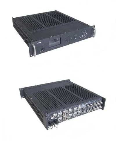
If you’re looking to standardize your time and frequency calibration processes, or if you need help verifying the results you’ve received, our team is here to support you. Don’t hesitate to contact our team to discuss your specific needs and get personalized guidance on calibration and verification workflows.
Time and Frequency Synchronization References
- Riley, W. J. (2008). Handbook of Frequency Stability Analysis. National Institute of Standards and Technology.
- Jones, R. E., & Stein, S. R. (2017). Traceability in time and frequency calibration. Metrologia, 54(3), 412-421.
- IEEE Standard for Definitions of Physical Quantities for Fundamental Frequency and Time Metrology – Random Instabilities. (2015). IEEE Std 1139-2015.
China Go-Sat Microwave Co., Ltd.
China Go-Sat Microwave Co., Ltd. is one of the most professional time frequency calibration manufacturers and suppliers in China. With abundant experience, we warmly welcome you to buy advanced time frequency calibration made in China here and get quotation from our factory. All customized products are with high quality and competitive price.
Address: No. 3908 ShiBo Avenue, Baqiao District, Xi’an, China
E-mail: sales@go-satcom.com
WebSite: https://www.go-satcom.com/
